
Community
Homemade Pikocores in the wild
A collection of homemade Pikocores and strange ports. It also covers alternate firmware and new enclosures. There are other remixes of the little sampler too.
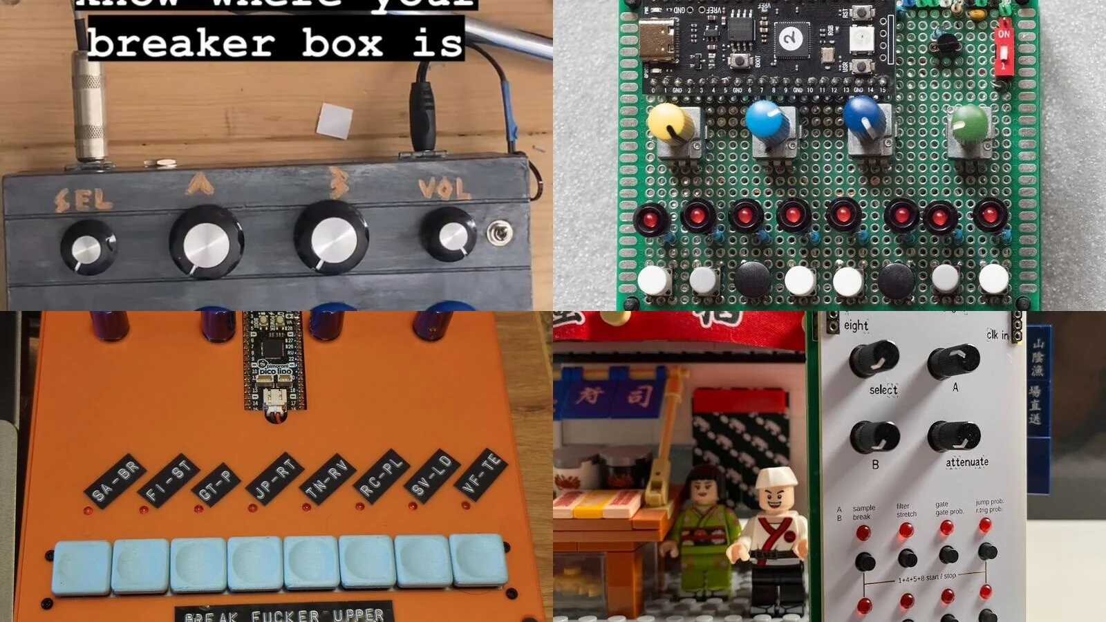
One of my favorite parts of making the Pikocore open-source has been seeing what people do with it. I made it as a very small sample mangler with eight buttons and four knobs. Some people looked at that and added arcade buttons or a screen. Others gave it a keyboard or moved it into Eurorack. A few redesigned the circuit board.
I started collecting these versions because many were scattered across social posts and YouTube videos. Others only existed in GitHub repositories. Some have complete build files and some have only a short video. They are all interesting to me because they show how much the physical interface changes the way the same firmware feels.
Here are sixteen Pikocore versions and related projects I could trace back to their makers.
starting with the schematic
The Pikocore source code, schematic, bill of materials, and DIY walkthrough are available online. That is enough information to build one, though it still leaves a lot of decisions for the builder.
The original Pikocore is intentionally cramped. I wanted something that could fit in a pocket and run from one AAA battery. If you make your own, there is no reason to keep those restrictions. Spread out the buttons or use parts you already own. You can even make the whole thing enormous.
Most of the builds below started with exactly that decision.
arcade buttons
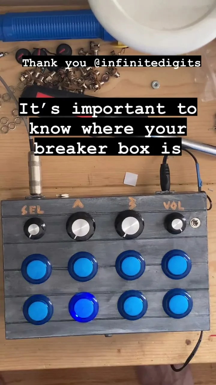
Ground Grown Circuits / Noah Jolly built one of the first large Pikocores I saw in July 2023. Noah replaced the small tactile switches with eight illuminated arcade buttons and put everything into a handmade case. It looks like something you are supposed to hit instead of cautiously press with one finger, which suits the Pikocore pretty well.
There was one useful note from the build. The LEDs in the arcade buttons could use some buffering to make them brighter. This is the sort of small problem that only becomes obvious once you take a circuit designed for tiny LEDs and connect it to something much larger.
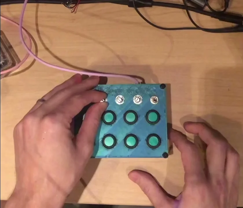
2ononen made another arcade version in a compact blue case. It has glowing green buttons, four knobs, and toggle switches across the top. The case is still small enough to carry around, but the buttons have enough room that you can play it with more than one finger at a time. A lot of the comments on the original post were simply people asking where they could get the enclosure.
Mid-Air went much bigger. Their Pikocore, documented by the 100% BOOTLEG channel, has four knobs and eight arcade buttons on a broad black panel. The build video includes construction photographs and also shows how to send a synchronization pulse from a DAW into the Pikocore.
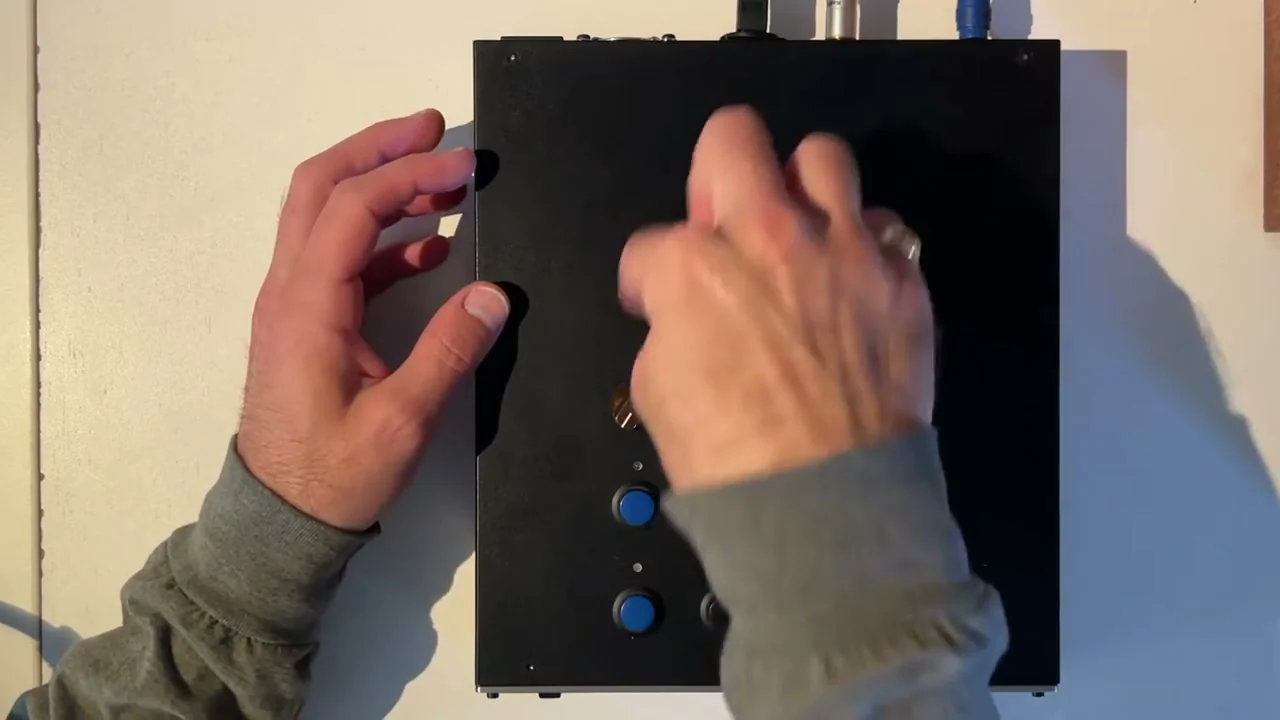
All three use nearly the same controls, but they feel like different instruments. The small blue box is portable. The Ground Grown Circuits version looks like a little arcade machine. The Mid-Air version gives both hands room to work.
building the circuit by hand
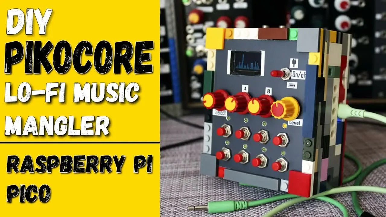
Andr DIY Music built a Pikocore around an RP2040 clone and added an ATTiny85 audio spectrum display. It ended up in a colorful brick enclosure with the tiny display moving along with the music. Andr published a short build video, a full 95-minute construction stream, the wiring, and a link to the ATTiny85 spectrum project.
I like that this build adds something completely unnecessary. The display does not make the sampler sound better, but it makes the machine more fun to watch and gives the finished object its own personality.
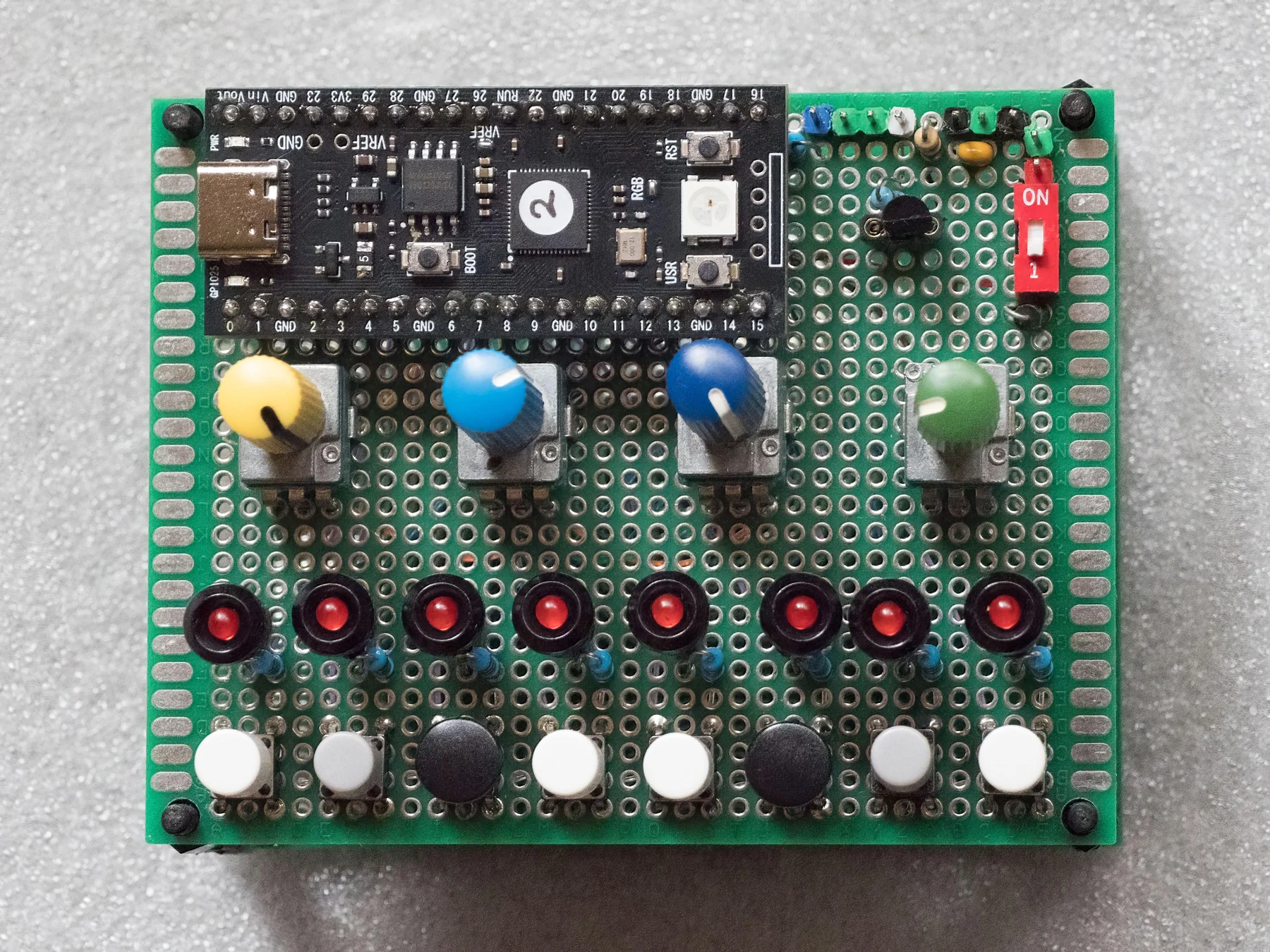
Reddit user bellabebop made the hand-built “Another 7×9” Pikocore on a large green board. It uses a 16 MB RP2040, four knobs, discrete LEDs, and two rows of four switches. The maker originally tried arranging all eight switches in one row, but found that two rows made simultaneous presses much easier.
The build thread has several practical details. Bellabebop recommended RK097 pots for a finished build and less expensive RV09 trimmers while breadboarding. They also spent several days tracking down a problem with simultaneous button presses, which is a good warning to test the combinations and not only each button by itself.
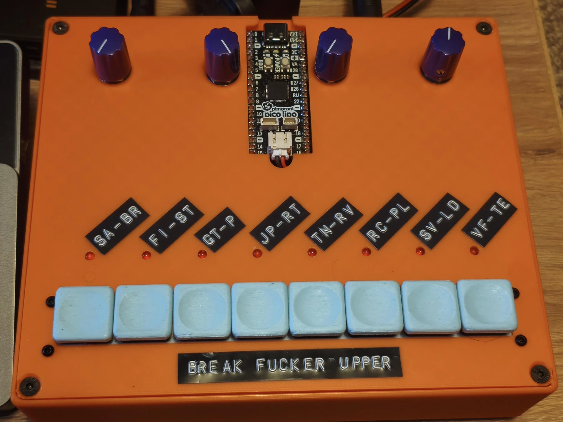
The “Break F**ker Upper” started on a breadboard before moving to perfboard. It finally got a custom orange 3D-printed enclosure. Reddit user Electrical_Lake9586 used a Pimoroni Pico LiPo with debounce capacitors and a flyback diode around the sync transistor. The case and buttons were printed for the project. The extra parts cost about £15 because most of the material was already sitting around the workshop.
The maker later shared a DIY Layout Creator diagram, but also said that the jack wiring should be checked and that the finished circuit had changed from the plan. I appreciate that kind of note. A photograph proves that someone got a particular board working, but it does not automatically make every earlier drawing a verified build guide.
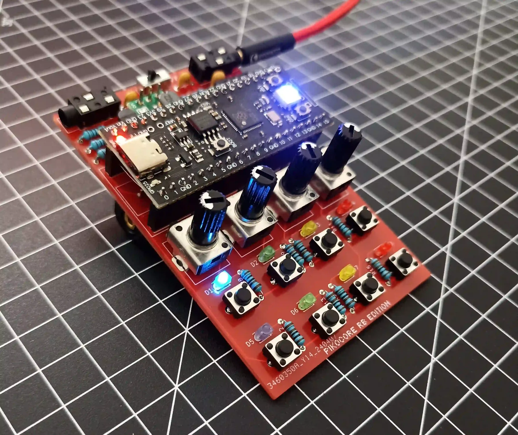
ivndbt redrew the Pikocore as a custom red PCB. The first board did not work because three resistors were missing. After adding them, it worked. This is a very familiar way for a homemade PCB to come into the world.
The build journal explains the process and the decision not to release the board files. This was a personal exercise in learning and documenting a circuit, while still encouraging people to support the original project.
These projects show several ways to get from a schematic to an instrument. You can wire the circuit directly or move it to perfboard. Drawing a new PCB is another route, with its own kind of debugging waiting inside it.
a new case can be enough
Edboy796 made a 3D-printed case that gives Pikocore the shape and colors of an SP-303. The second revision added clear resin buttons and room for one AAA battery. It also had holes sized for Thonk trimmer caps. The holes still did not line up perfectly with the knobs, so a third revision was planned.
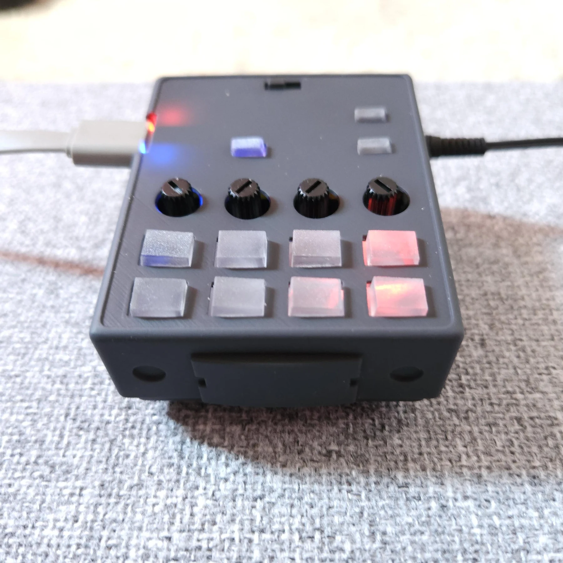
Nothing changed in the firmware, but the case makes Pikocore look like it belongs to a completely different family of samplers. I like it because the familiar shape changes how I approach the instrument before it even makes a sound.
modular pikocores
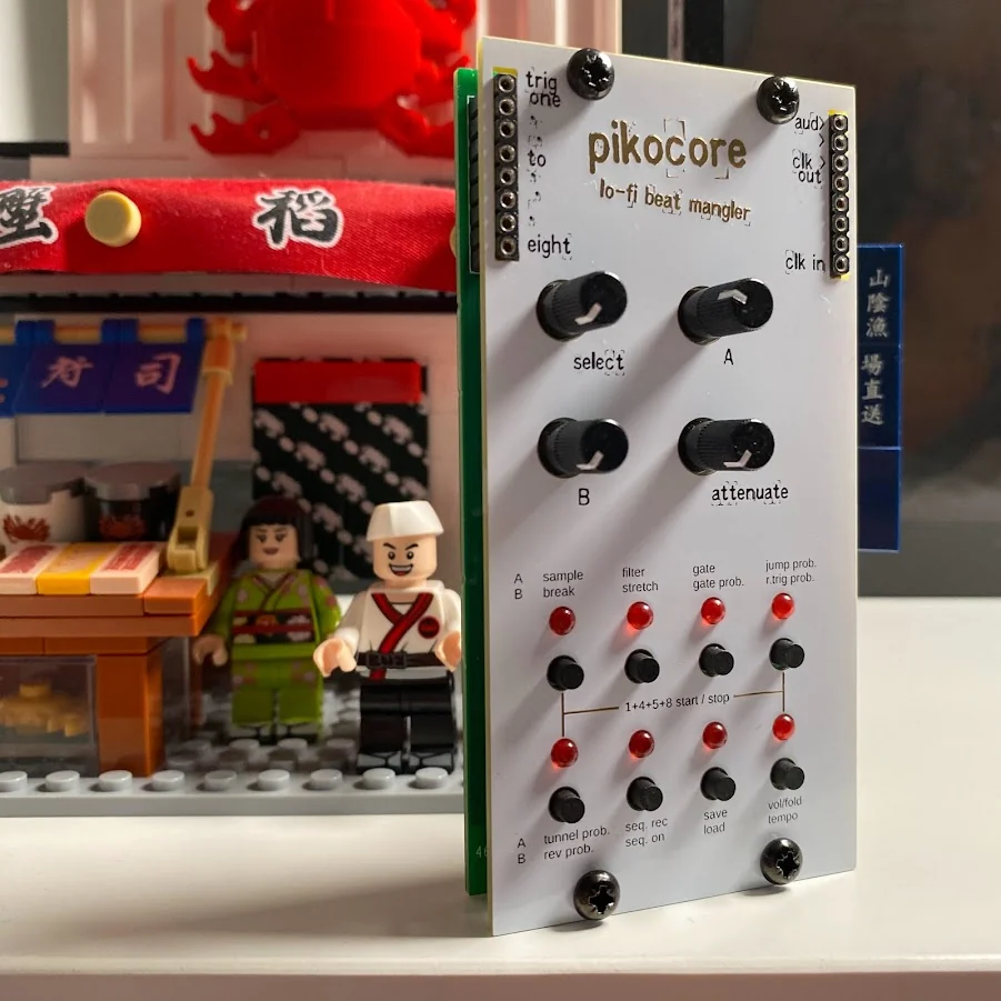
The Faux Cyrillic AE Modular Pikocore puts the circuit behind an AE Modular panel. More importantly, the project includes the things needed to reproduce it: a schematic, BOM, pick-and-place data, panel files, and fabrication archives. The repository is GPL licensed.
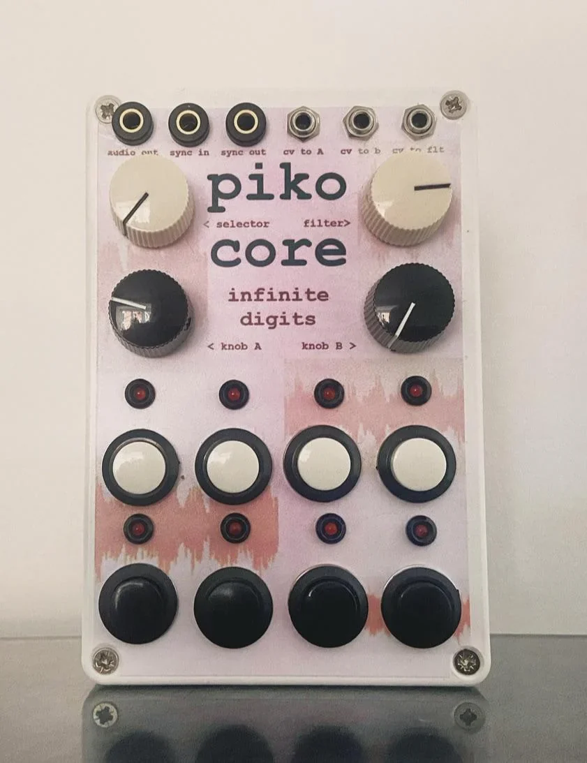
Reddit user Strange_Ad8259 added CV connections to a custom pink Pikocore. Alongside the audio output and sync in/out, the top edge has jacks labeled for knob A, knob B, and the filter. The four-knob, eight-button layout is still familiar, but now the rest of a modular system can reach in and move it around.
This one appeared in the replies after I asked people to share builds I had missed. It is exactly the kind of thing I hoped would keep happening when I published the schematic.
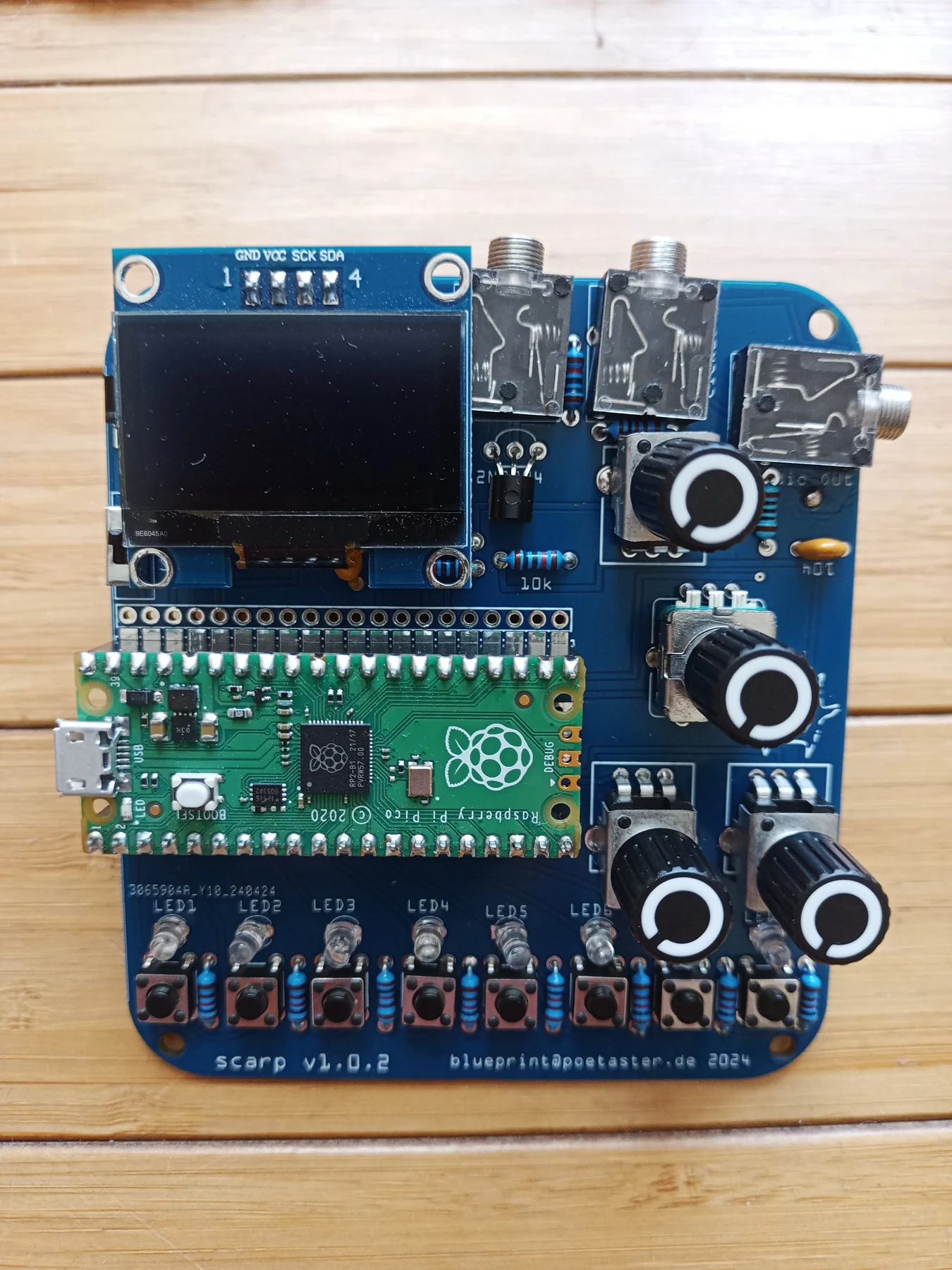
Scarp, made by Poetaster, is a larger open RP2040 music platform inspired partly by Pikocore. It has eight LEDs, an encoder, extra GPIO, and options for an I²C display and I²S audio. Pikocore is one of several instruments that can run on it. The Scarp repository includes the hardware and Gerber files.
There are commercial modular versions too. The Erica Synths Pikocore XL, P4L Modular PIKOCOREURO, and Maneco Labs Pikoloops all make more room for the controls and connect Pikocore to a modular system. They are commercial instruments rather than homemade one-offs, but all three answer the obvious problem with a very small Pikocore: the controls are very small too.
putting pikocore into unexpected hardware
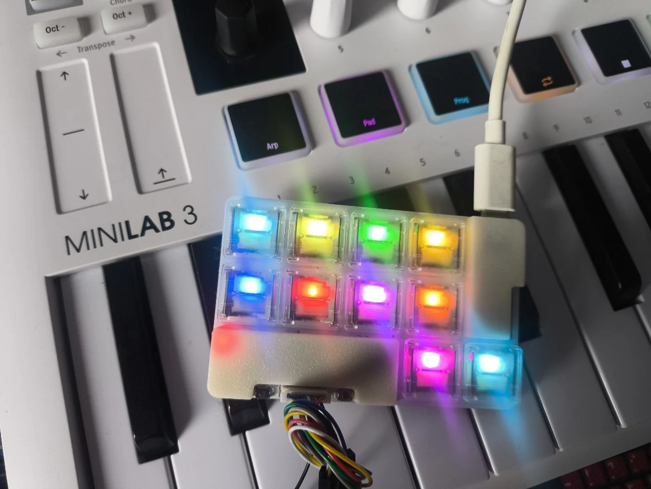
Nizkore runs Pikocore on the ten-key PNCATEHO low-profile keyboard. Since there are no continuous knobs, keys and modifier combinations take over the original controls. USB MIDI can control playback and effects as well. The same device can still be used as a normal computer keyboard, which is probably the strangest dual purpose Pikocore I found.
Both the Nizkore firmware and PNCATEHO hardware are published.
The Pikocore GamePi13 port runs on a Waveshare RP2350-PiZero with a GamePi13 handheld interface. It has a 240×240 display showing the BPM, sample name, waveform, playhead, mode, and current parameter values. The twelve console buttons replace the eight buttons and three knobs. The port also saves its state and has a USB sample-bank loader.
This is more of a software and interface port than a homemade clone. The source repository is useful if you want to see how far the front end can change while keeping the audio engine.

a few mysterious ones
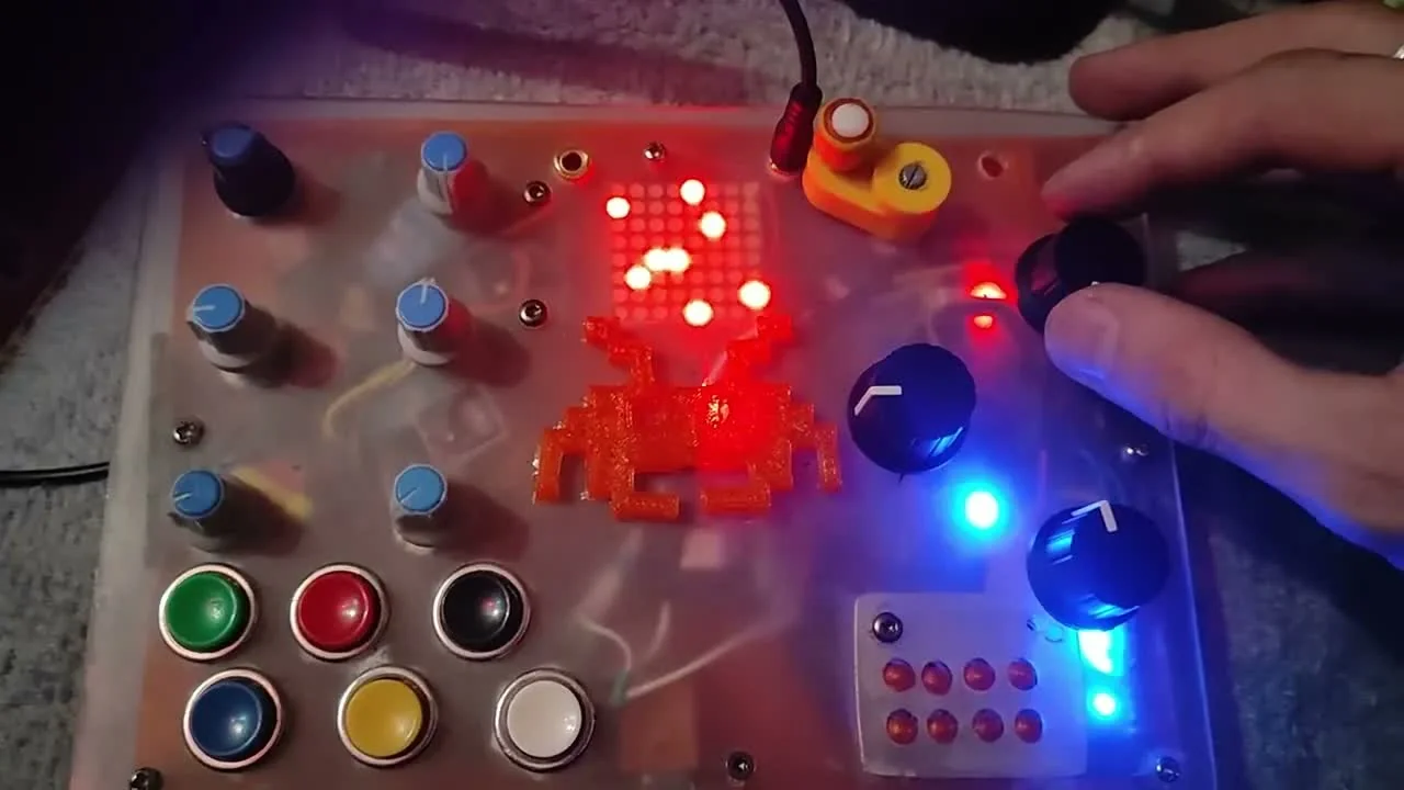
Not every project comes with a build guide. PicoMonster is described as “Pikocore + Mutant Synth.” There is a video of the finished hybrid, but I could not find a schematic or construction files for it.
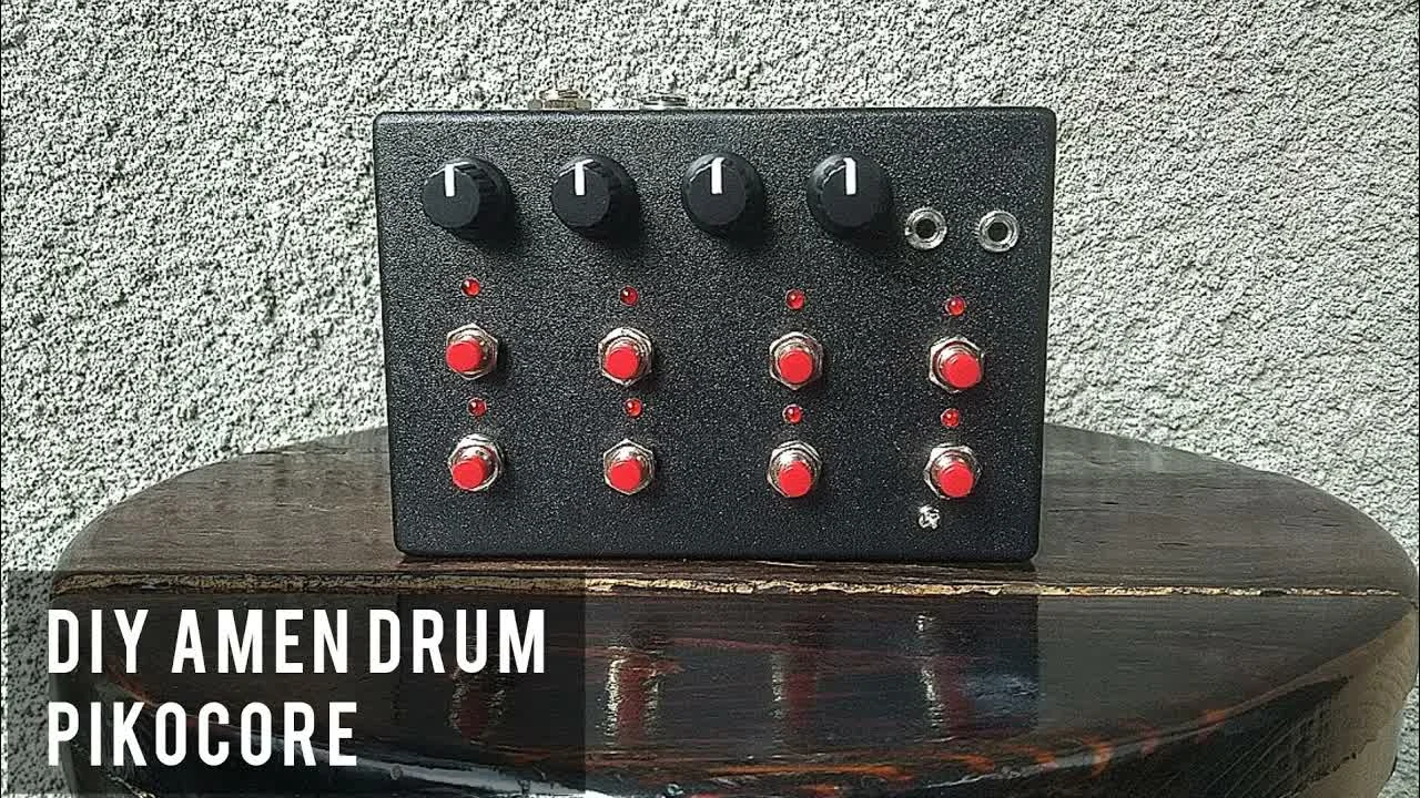
The DIY AMEN DRUM Pikocore is another personal build documented mainly by a play test. The video points back to the original project instead of offering separate files. It will not help much if you are trying to reproduce the enclosure, but it does show another Pikocore assembled at home.
Russian builder Хрустэффект posted a Pikocore in a “new design” and linked the video to VK and Telegram communities. It looks like a custom or small-batch redesign, though I did not find public fabrication files.
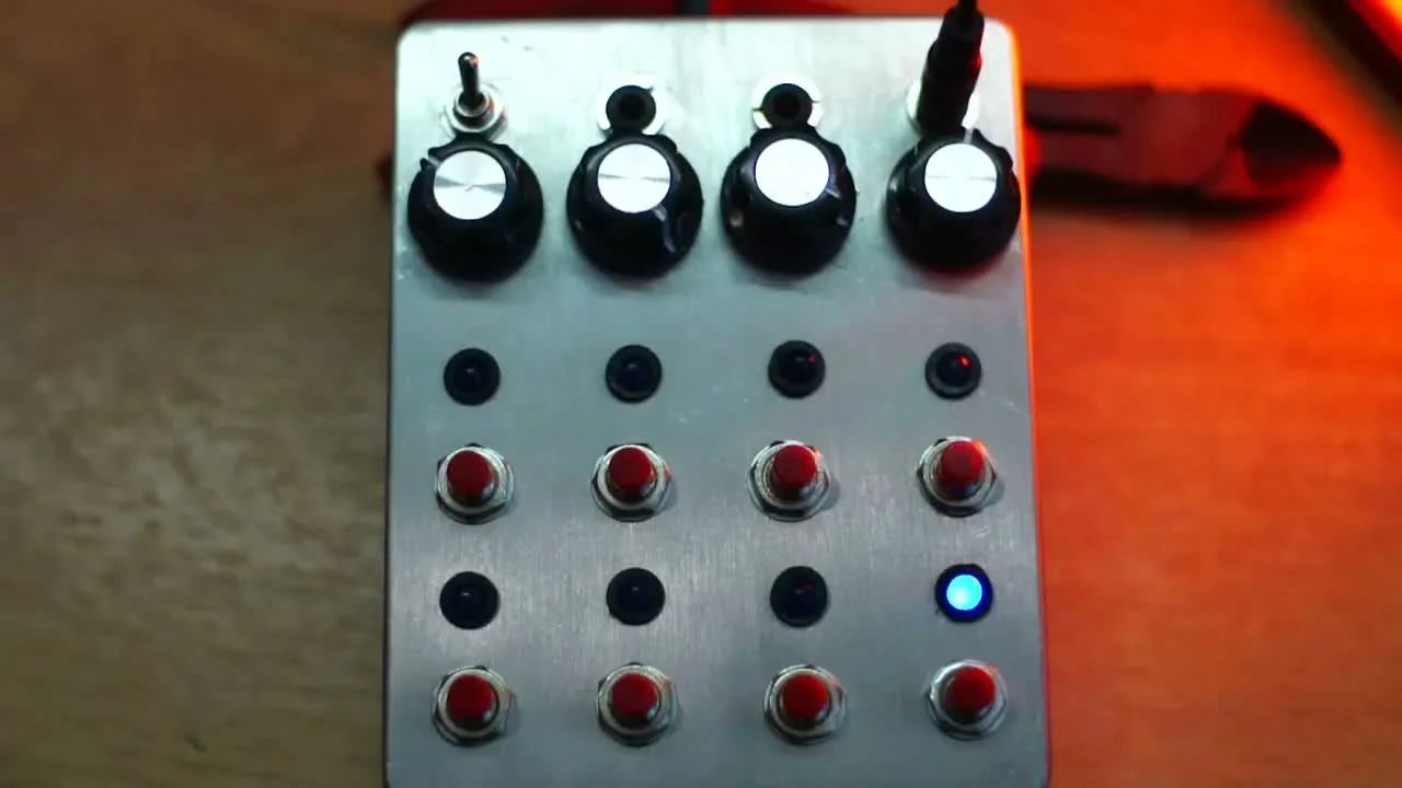
I included these because many good homemade instruments never become repositories. Sometimes the only documentation is a camera pointed at the finished thing, followed by several minutes of noise.
alternate firmware
The box can also become a different instrument without changing any hardware.
PikoBeats by rheslip turns it into an eight-track sample player with a Euclidean sequencer on each track. Piko-33, also by rheslip, is an eight-track, 16-step sequencer with pitch, velocity, and probability for each step. The pikocore_firmz collection has still more experiments.
Poetaster's version of PikoBeats revisits the Euclidean player with controls for track and sample selection, fill density, repeats, pitch, volume, and tempo. ni9aii's Pikocore fork works with Piko Upload, a Rust USB-CDC program for moving samples onto the device.
The original firmware keeps changing too. Pikocore v2.4.0 was released in August 2026 with improved clock synchronization. It makes me happy to see people changing the firmware while I keep changing it too.
some notes if you are building one
A few useful things came up repeatedly while reading through these projects:
- A 16 MB RP2040 gives you much more sample space than a 2 MB Pico. Make sure you build the firmware for the flash size you actually have.
- Test the circuit on a breadboard before moving it to perfboard. The audio path and clock wiring are much easier to change there, including the jacks.
- Test simultaneous button presses. A layout can work perfectly one button at a time and still fail when you mash it.
- Large illuminated buttons may need more thought about their LED power and buffering.
- A schematic is not a PCB layout. Redrawing it gives you another opportunity to omit three resistors (or invent a new mistake of your own).
- Treat an unverified community wiring diagram as a useful lead, not a guarantee.
send me yours
This list only includes Pikocores I could connect to a public post and a maker. There are certainly more in private accounts and old Discord messages. Others are sitting on workshop tables or desks where nobody thought to take a photograph.
If you made one that is missing, send me a picture and a link. Pikocore remixes genuinely light up my day (sometimes literally, depending on how many LEDs were added).
Made by Infinite Digits
Shop this story

Build your own
pikocore kit
The complete through-hole kit for making a Pikocore at home.

Start from the board
pikocore circuit board
A Pikocore circuit board for builders sourcing their own components.

The original
pikocore
The pocket-size lo-fi sample mangler that started this family tree.